Sidebar
Table of Contents
Preparation of samples for NanoSIMS analysis
Sample preparation is a big part of the NanoSIMS analysis, and there is no general rule for how to do it best. Basically, it's like cooking — one needs to adhere to some basic guidelines, but the result will differ from cook to cook. Since many people have used NanoSIMS as one of the analytical methods, it is best to seek inspiration and useful tricks in published literature. A good starting point may be the list of papers compiled according to a given theme by Cameca or in a recent review by Hoppe et al. (2013). Samples prepared for other techniques such as TEM or SEM are usually good also for the analysis by NanoSIMS, so seeking expertise from people in this area may also be very useful.
Sample dimensions
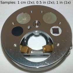
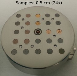
An important constrain on the samples for NanoSIMS is their size. Presently, our sample holders support discs with a diamater of 0.5 cm, 1 cm, 0.5 in and 1 in. Note that the outermost ring of about 0.5 mm thickness is unusable due to coverage by the holder rim. The thickness of the sample can be in the range 0.1-1 mm (e.g. a glass disk or a filter) or in the range 4-5 mm (e.g., a resin-embedded sample).
Basic guidelines of sample preparation
As touched upon in the introduction to NanoSIMS, the samples need to be
- dry - this means they should contain minimal amounts of volatile compounds such as water or oils, and allow reaching the desired vacuum in the analytical chamber of <1×10⁻⁷ Pa (see the note on resin-embedded samples below)
- flat - remember, small surface irregularities may look like mountains under NanoSIMS;
we recommend a final polishing step using 30-50 nm Aluminiumoxide particles;
polishing facility is available at Utrecht University.
If samples don't need polishing, for example flat crystal surfaces, the topography of the sample surface has to be less than 100 µm. - thin - this is important when you want to combine the NanoSIMS images with other imagery, such as TEM or fluorescence imaging
- conductive - if the sample itself is not conductive, a thin conductive layer needs to be deposited on top of it, preferably just before placing the sample in the NanoSIMS instrument;
facility for Au deposition is available at Utrecht University
Additionally, they should be
- able to withstand high electrical fields
- compact - that is, not contain any “loose pieces” that could detach if the sample is placed in a vacuum; to ensure this, we use dry nitrogen gas to blow away any such pieces before we put the sample into our vacuum chamber
For microbial cells in a suspension, filtration on a standard polycarbonate filter (0.2 micron pore-size; see for example here) followed by drying and deposition of a thin Au-film works well. Deposition on a glass slide (its size must be compatible with the sample holders; see for example here) also works well. For microbial cells in sediments, separation of the cells from the sediment should be tried first, followed by deposition on a filter or a glass slide. In both cases, when preparing cells from water samples that contain dissolved minerals, washing with MilliQ before deposition on the filter/glass slide is advisable to minimize the formation of microcrystals during the drying procedure.
For samples such as tissues, sediments, or soils, where preservation of the spatial organization of the constituents is important, embedding in a resin or wax can be done.
When studying elements/compounds that diffuse easily within cells or are soluble, steps used for chemical fixation of the cells, which are known to remove the soluble compounds or redistribute the diffusible compounds, should be kept at minimum. Shock-freezing followed by controlled thawing has been shown to lead good results (REF).
For both resin/wax-embedded and shock-freezed biological samples, the sample should be cut in thin sections using a microtome. For resin-embedded geological samples, polishing is necessary.
Resin-embedded samples
The resing-embedded samples need to be between 4 mm and 5 mm high.
A number of people use Araldite (502 26 g) as the resin of choice.
The resin will contain traces of volatile compounds that will outgas when the sample is exposed to the vacuum. To be able to reach the desired vacuum of <1×10⁻⁷ Pa in the analytical chamber, this outgassing rate should be kept at minimum. This can be helped by casting the sample for example in a metalic ring that is gas-impermeable and also non-magnetic. Such rings (diameter 1 cm, height 0.5 cm) can be purchased from Cameca. Additionally, polishing of both front and back sample surfaces will help minimize the total surface area through which outgassing occurs.
We ask you to deliver the resin-embedded samples at least a weak prior to the scheduled measurement, so that we can start the degassing process early enough.
For some types of analyses it may be not so convenient to have an organic resin as an embedding material, for example when analysing small organic inclusions in porous materials. In such cases, Woods alloy might be a good alternative.
Marking
Fields of view analyzed by NanoSIMS will be very small (typically from 1 to 100 microns), which makes it difficult and often time-consuming to locate them on a sample of several tens of square-mm in size. We ask you to make high-resolution images of your samples (the entire sample, or at least a major part of it) and mark in these images the fields of view that you wish to analyze by NanoSIMS (a low-resolution example of a clearly annotated image is shown here). These images should be submitted together with the samples. This will significantly enhance the efficiency of the NanoSIMS analysis, as we will be able to measure straight away the fields of interest rather then spend time locating them first. Note that if you do not provide these kinds of marked images, we will analyze only randomly selected areas.
A possible approach for marking is to use a laser dissection microscope to mark fields of interest by ablating material around them with a strong focused laser beam. Although quite sophisticated, this technique does not always give satisfactory results, as the marks are often not clearly visible by the NanoSIMS CCD camera.
A simpler approach is to use navigation based on co-ordinates. First, take a high-resolution image of the entire sample, which can be done by stitching together microscope images of the sample obtained at a lower-magnification but with a high pixel resolution camera. Then, mark co-ordinates of 3 prominent “landmarks” as well as of the regions of interest. Since viewing of the sample in the NanoSIMS chamber is aided by a CCD camera, the three landmarks will be easily located. Subsequently, real positions of the regions of interest in the NanoSIMS can be easily found using the noted co-ordinates and some simple algebra. A spread-sheet implementing this calculation is available here.


